Having recently bought a Commodore 128 again after not seeing one for many years I just had to try out all the things I never got to do as a kid. One of which, colour output on the 80 column mode.
We had a monitor for 80col but it was Monochrome only.
It was only when researching the output I discovered that it is basically CGA compatible (and I could have used any old CGA monitor back in the day!) so I set about making an adapter to connect to a normal SCART TV.
There are many designs on the net but I didn’t like the look of the washed out and/or blurred images they created. So I decided to create my own clean perfect adapter.
The concept sounds simple. Turn R, G, B, I digital signals (4bits) into RGB analogue signals.
There is one last thing, CGA replaces one of the yellows with brown. I don’t know why, maybe just to get a bigger colour variation but it’s done inside the monitor. If I was to make a SCART adapter it had to do this conversion too.
Existing designed used resistors and diodes to pull signal levels all over the place. I decided to use logic gates to create a clean signal.
So, 3 and gates with one side on the R,G and B signals and the other on the I gate turn R,G,B,I into RRGGBB, 1 bit plus intensity is turned into 2 bits per colour. From there a simple 2 resistor DAC makes a signal I can use in Scart.
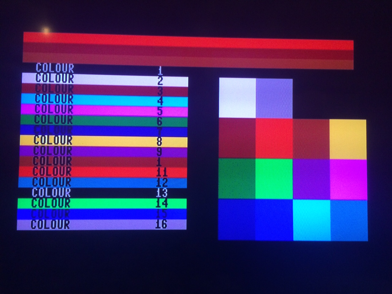
This is where I made my first mistake. Sadly I didn’t realise that I on it’s own was a valid colour (Dark white) so the and gates don’t pass I on it’s own and as such it appears black 🙁 I didn’t discover why until well after the boards were finished and it was too late to fix. So take note, when working out your logic make sure you account for EVERY situation you need to.
SCART required composite sync while CGA has H/V sync. A simple logic gate takes care of that to combine both signals. Another gate is used to invert the output (selectable with a jumper) so you have a choice of positive or negative sync depending on if you use real SCART or an RGB to VGA adapter of the type found on eBay.
The brown fix had to detect a particular set of inputs and lower one of the colours. a line selector was used for this and pulls down the voltage on green when brown is needed.
Some math was needed to get the levels right for SCART, you have to take into account the internal resistance of the input as well as any resitors in the circuit.
One of the other issues with the VIC-II (not the 80 col output) is the levels on Luma-Chroma are often incorrect for modern S-Video inputs. A simple fix is an inline resistor. I wanted to take 5v from the video output so I had to have a plug there anyway it made sense to pass through the VIC signals on my board so the new board connects to both video outputs and has a single output for SCART which in combination with a switch allows easy swapping of 40/80 column mode on the SCART plug. No more unplugging!
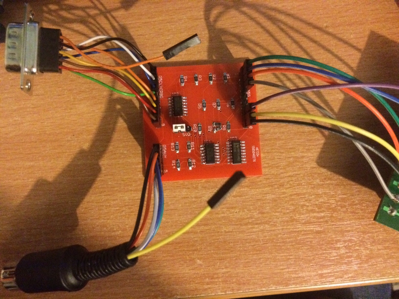
Anyway, the final circuit layout was sent off for PCB manufacture and a load of surface mount ICs and resistors were used.
